Live Well Conversion for Your Fish Box
When I bought my convertible one of the first things I began to plan for was a live well. It was originally constructed with one in the floor, but that design was not really accepted by many buyers. It was small, square and took up a large amount of storage space. In reality, I would only use this live well on occasion, so I decided to 1) try to cause minimum damage and rebuild to the boat and 2) make it temporary, to use only when I needed a well.
The existing fish box from the sportfish floor could make an excellent live well.
On this boat there exist a large, heavily reinforced fish box located centrally in the floor against the transom. I calculated the volume and if used it could give me a 45 gallon well. Other pluses include that there once was an in-floor fish box that was plumbed. There was a macerator pump already hooked to the fish box, There was an unused 1.5” through hull proximate to the box, and the box is insulated. There are quite a few cons to an in-floor fish box which many of you could guess. One big issue would be that it is in the floor, under your feet. Other issues would be that a portion of this one is very close to the water line, it is long with only slightly rounded corners, I would have to use a large cooler for fish if it is used, and it is not blue. Knowing that I would only use it on occasion and that I could overcome many of the negatives I decided to go with the change.
Please do one thing before the first purchase or cut - Plan. Do drawings, make parts list, make it work on paper. I do this with every project, and you would be surprised at how many ideas do not end up working.
1. Determine the fittings and locations from your setup.
The first thing I did was to measure all the penetrations as well as the thickness of the shell and the insulation. There was only one penetration since another had been filled in. I would leave that one alone since it was the macerator pump drain.
Next I calculated the flow rate I would need. I wanted to have at least 10 water changes per hour. I had a 1.5” through hull for a drain from the old live well. I had a 2”through hull that was part of a defunct wash down system. The longest run of piping would be 5 feet. I also had four spare Rule 3800 pumps. This pump could be installed below the waterline as required. Once installed it could provide up to 3660 gallons per hour. Using the internet for information it seemed that the maximum gravity or low-pressure flow through my 1.5” drain would be 2100 gallons per hour. I was shooting for a 10X water change on a 45 gallon live well, so I needed 450 gallons per hour. It all seemed to fit my spec.
From all of this information you can determine the types of fittings you will need for plumbing. Since the insulation was 1 inch thick I felt it would be best to have fitting that tightened on the shell only. I selected a 1.5” bulkhead fitting for the incoming water and would place that hole on one side of the bottom. I selected a 2” bulkhead fitting for the drain which would transition to 1.5” about 1 foot from the hull penetration. Even though the drain line is a 1.5” though hull I wanted to attempt to get some gain from a higher pressure and lower velocity from the bigger pipe causing water to move faster through the last 12 inches of 1.5” pipe. If that really happened who knows.
Shown is the selected 2” bulkhead with threads both inside and out.
Check all clearances before cutting. You would be surprised how much space these take up.
1. Prepare the fish box for construction.
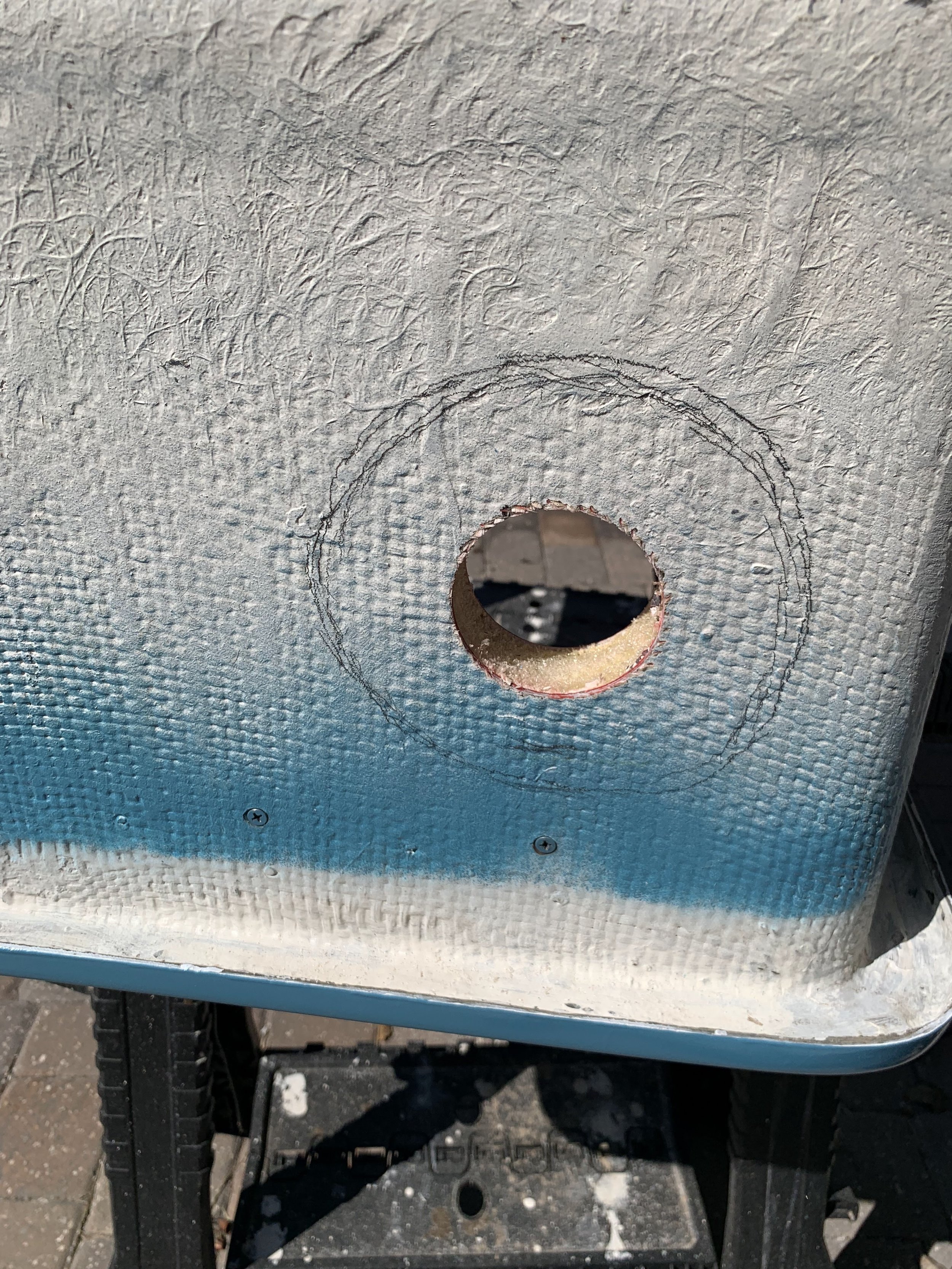
I noted earlier that one problem is that the box is not blue. Everyone knows that is an easy fix. Prior to this I need to prep the box with all of the cuts needed to make it all work. This is something that I did not do but luckily I did not damage the paint. In the pictures you can see that I cut back the insulation, then glassed the circumference, to make the fitting workable. I also lightly sanded the entire surface with 220 grit paper. To drill the holes, I used a nice quick snap hole saw attachment for both holes. For the insulation I used a grinder fit with a cutting wheel. A couple of tips-make sure you clean all of the foam insulation off of the shell and then remove about 1” more from between the shell and outer jacket. I filled this gap with fiber reinforced Bondo prior to laying up the cloth and resin.
Note the insulation and the inner and outer skin.
A cutting circle for the exterior skin was determined by how much space it would take to effectively mount each bulkhead.
Make sure the insulation is completely removed and that you can seal the inner and outer skin together.
Notice how much bigger the exterior hole had to be in order to mount the bulkhead.
The gap between the skin and shell was filled with fiberglass reinforced Bondo.
Once the Bondo cured the circle was tabbed and sealed with resign and mat.
1. Painting.
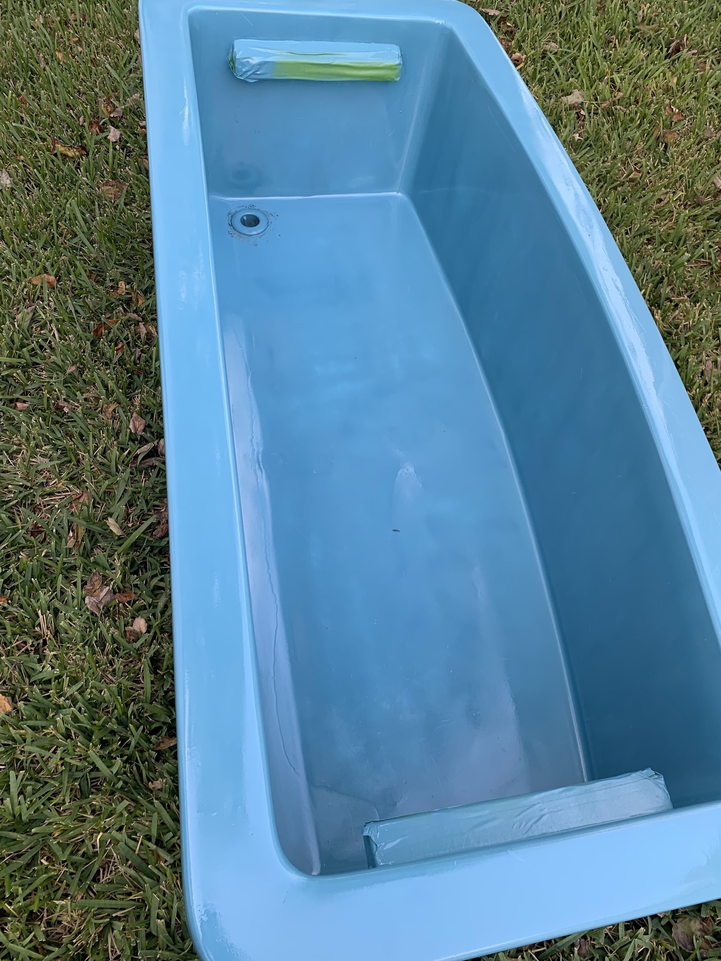
There are two areas to be painted. I painted the outside of the shell where the hole penetration was prepped with white enamel with primer. I used Rust- Oleum Painter’s touch 2x spray paint. I then taped the sides, edges, and holes off for the interior paint. Prior to painting I used acetone to wipe the surface down. Please note that this is a very string solvent and should not be used in great amounts. I then used a two-parts spray paint which I had used for other marine applications successfully. It took two cans of Samurai 2-Part Paint to achieve the coverage I wanted. The blue box is not visible on the deck since there are two large lids over it. A couple of notes on this paint-It is NASTY, and it will get all over everything. I choose a non-windy day and outside to compete this. Make sure you still wear PPE (Personal Protective Equipment) to do this. In the end it is worth it since it gives a hard gloss finish.
This two part polyurethane paint has been used for many of my marine applications including clear-coating graphite and painting parts like this.
This was an Amazon purchase and is readily available.
Note the blue color. Baits tend to remain more calm in a blue tank verses a white tank.
The existing macerator drain is shown minus the screen. It took two complete cans to get the finish just right.
Painting is almost complete.
This was definitely an outside task and PPE was worn during each spray.
1. Install your fittings.
I choose fittings which had an integral plug. This would allow me to use this a as fish box, which is what I do most of the time, and not get fish debris in the hoses. I also installed an incoming plug which had external threads since I wanted to add a removeable spray bar. The drain line would be fitted with standard fittings and a screen that drained at the 45-gallon volume mark. I used a Stainless-Steel Tri-Clamp fitting on the incoming line close to the fish box penetration. I used a Cam Lever coupling on the drain line at the fish box penetration for quick removal. When installing these fitting it is important to note how the box is installed. Is it possible a fitting could prevent the box from being moved in and out? I had to watch this since the end clearances were tight.
Each bulkhead was sealed the same.
3M 5200 was used since there was no intention of removal in the future.
Both bulkheads were fitted with plugs for when used as a fish box.
1. Install the hoses and pumps.
Fortunately, I had all of the hardware and pumps in place from old systems. You may have to install your own. Note that the pump is mounted to a glassed-in base plate. The pump was also pre-wired to a breaker in the engine room. Note that the through hull is bonded. For safety and sanitary reasons, I installed another ball valve in the incoming line proximate to the inlet. The ball valve would also allow me to throttle down the incoming water to match the drainage rate. For my install this was the area which could cause significant hull breach though failure of a couple of components. Due to this I used Marine Exhaust and Water line, used two clamps on everything (as you always should below the water line) and made sure that the hoses would not contact anything else on the boat. I would like to note that the system through hull is always valved off except when in use. I think the weakest link in the system would be the connection to the Rule pump since the nipples on the pump are smooth and have no ribs. In addition, they are plastic. If you are no comfortable with this then there are many other pump options.
Incoming 1.5” line.
Note the SS Tri-Clamp and the bronze ball valve.
The unused salt water wash-down made things easy.
Note that the pump is mounted to a pad and that all clamps are doubled up. The waterline is approximately half way up the exhaust pipe in the pic. Don’t worry, all electrical and hoses were secured following completion.
You can see that clearance for this fitting is very tight.
The Cam Lever fitting made the removal of the box easy. Please check the levers periodically for corrosion as they will need replacing over time.
1. Connect and Test.
My first test was for ease of removal. I wanted to make sure I could access all of the other components if I implemented this. Note that this should have been tested early on and in fact it was, but once everything is added problems can arise. I fabricated a “T” bar with 3/8” holes to push water into all potential dead spots. I placed a 90 on the drain with a Stainless screen insert. I bought all of these on Amazon. I turned the system on and then used the ball valve to adjust the flow. Once it was turned off I turned on the macerator pump and let it gravity drain. It worked great! Even better, I removed the drain fittings and the T bar and plugged the holes-fish box again!
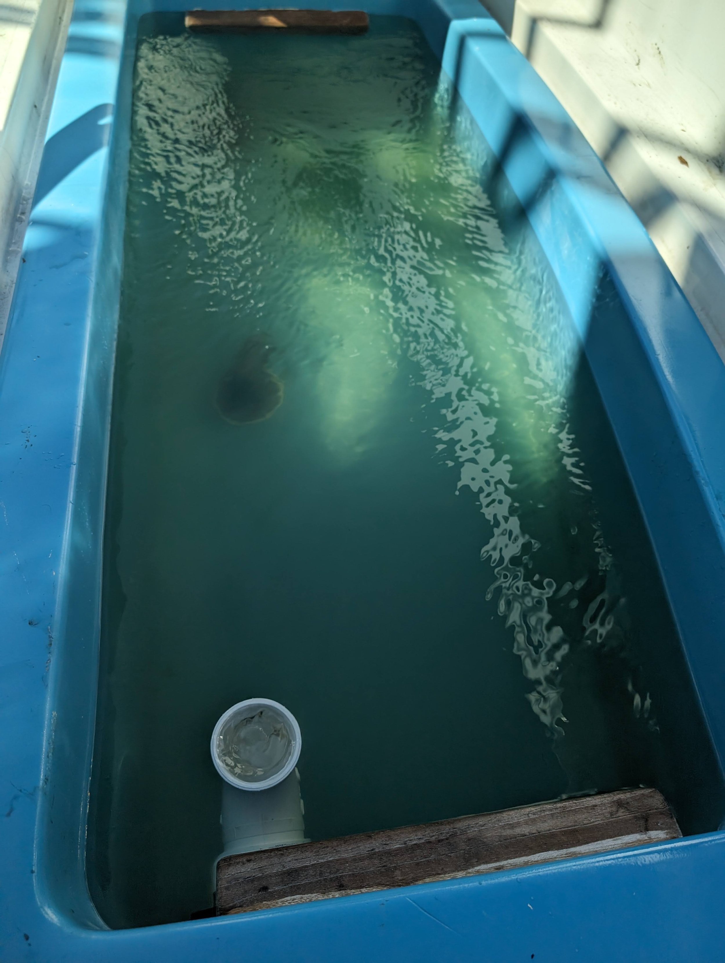
During the initial fill the circulation was observed. A Spray bar may decrease the dead spots and still have high flow due to the capacity of the pump.
The drain is located at the 45 gallon mark. It was not filled to the top of the box.
The flow was healthy.
This was the existing 1.5” line that remained from the removed OEM live well.
A “T” and a screen were added to the inlet and outlet.
The blue color remains unseen when the covers are on.
Tight Lines and on to the next project!
UPDATE: I have removed this system from my boat. In order to keep using this I would need to place a seal of some kind on the lid to prevent water from sloshing out while on the way. This water set off my bilge alarm intermittently and literally drove me crazy while fishing. I decided not to move forward with this since it would impact other drainage systems on the boat. So you win some and you loose some.
Scott


